


welding-rotator
A welding rotator is a device that drives the cylindrical (or conical) weldment to rotate by means of the friction between the weldment and the active roller. It is mainly used on a series of large machines in heavy industry.
A welding rotator is a device that drives the cylindrical (or conical) weldment to rotate by means of the friction between the weldment and the active roller. It is mainly used on a series of large machines in heavy industry.
A welding rotator is a device that drives the cylindrical (or conical) weldment to rotate by means of the friction between the weldment and the active roller. It is mainly used on a series of large machines in heavy industry.
The characteristic of a welding rotator is to apply pressure during welding without adding filler material. Most pressure welding methods such as diffusion welding, high-frequency welding, cold pressure welding, etc. have no melting process, so there is no problem of beneficial alloy elements burning like fusion welding and harmful elements intruding into the weld. The welding rotator simplifies the welding process. , It also improves welding safety and health conditions. At the same time, because the heating temperature is lower than that of fusion welding and the heating time is shorter, the heat-affected zone is small. Many materials that are difficult to be welded by fusion welding can often be welded by pressure welding to form a high-quality joint with the same strength as the base material.
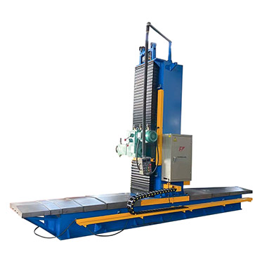
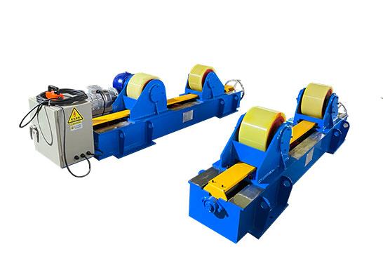
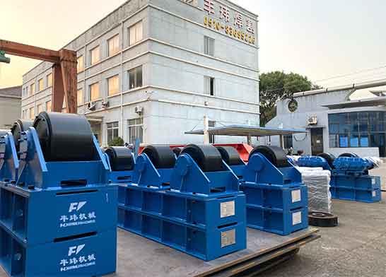
A welding rotator is a kind of welding auxiliary equipment, specifically a kind of welding rotator, which is often used for welding inner and outer circumferential seams and inner and outer longitudinal seams of cylindrical workpieces. It consists of a base, a driving roller, a driven roller, a bracket, a transmission device, and a power device drive. The transmission device drives the active roller and uses the friction between the active roller and the cylindrical workpiece to drive the workpiece to rotate to realize displacement, which can realize the horizontal position welding of the inner and outer circumferential seams of the workpiece and the inner and outer longitudinal seams. The automatic welding equipment can realize automatic welding. , It can greatly improve the quality of welds, reduce labor intensity, and improve work efficiency. The welding rotator can also be used with manual welding or as a device for testing and assembling cylindrical workpieces.
working principle
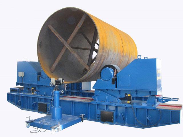
The transmission device drives the active roller and uses the friction between the active roller and the cylindrical workpiece to drive the workpiece to rotate and realize displacement, which can realize the horizontal position welding of the inner and outer circumferential seams of the workpiece and the inner and outer longitudinal seams. The automatic welding equipment can realize automatic welding.
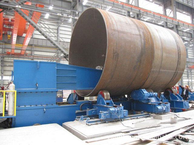
Mainly used for cylindrical assembly and welding. If the height of the main and driven rollers is adjusted appropriately, the assembly and welding of the vertebral body and the segmental unequal rotation body can also be carried out. For some non-round and long weldments, if they are installed in a special ring clamp, they can also be assembled and welded on the welding rotator. The welding rotator can also be used with manual welding as a device for testing and assembling cylindrical workpieces. The use of a welding rotator can greatly improve the quality of welds, reduce labor intensity, and improve work efficiency.
What types of welding rotators are there? Here is the classification of welding rotator:
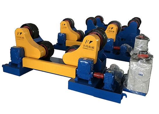
Self-adjusting welding rotator
The self-adjusting welding rotator is a displacement device that uses the friction between the active roller and the weldment to drive the workpiece to rotate. The swing angle of the wheelset can be automatically adjusted according to the diameter of the workpiece, and the center can be automatically adjusted. It is mainly used for the assembly or welding of cylindrical workpieces such as pipes, containers, boilers, oil tanks, etc. When matched with a welding manipulator and welding power source, it can realize the welding of the inner and outer longitudinal seams and the inner and outer circumferential seams of the workpiece.
 Self-aligning welding rotator
Adjustable welding rotator
The adjustable welding rotator consists of a driving wheel and a driven wheel. The active roller operation is driven by two motors respectively. Through the speed-regulating motor, the speed-regulating controller realizes step-less speed change through frequency conversion speed regulation or electromagnetic speed regulation. The linear speed of the workpiece rotation is 6-60 meters/hour, which can meet the needs of manual welding, automatic surfacing welding, automatic submerged arc welding, and other different welding needs, as well as various riveting of the workpiece. The distance between the main and driven rollers can be adjusted by screw or screw division to meet the welding requirements of workpieces of different specifications.
 Adjustable welding rotator
Non-self-adjusting welding rotator
The non-self-adjusting welding rotator relies on the roller seat on the movable support to adjust the distance between the rollers.
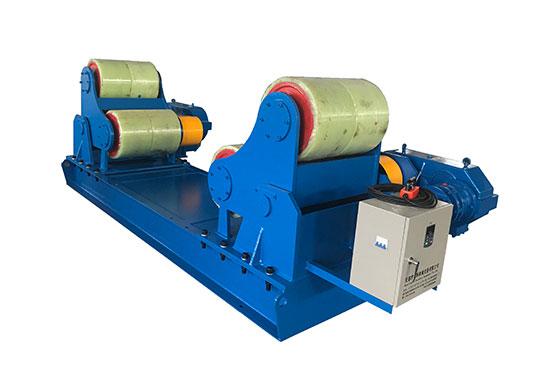
Anti-channeling welding rotator
On the basis of the adjustable welding rotator, the anti-sweep welding rotator is made into a liftable type with the roller of the driven frame. The photoelectric encoder is used to detect the amount of movement of the workpiece, and the system controller controls the lifting of the driven roller. The displacement detection frame is placed at one end of the workpiece, and the detection wheel is pressed on the end surface of the workpiece (the end surface must be processed). The detection wheel can rotate with the workpiece. When the workpiece moves axially, the detection wheel will follow the workpiece, and the photoelectric coding The detector detects the movement amount and direction of the workpiece, and its signal is input to the system controller for processing. The controller will adjust the lifting stroke, lifting speed, and lifting interval time of the driven roller according to the amount of movement, and control up or down according to the direction of movement. The amount of movement of the workpiece always fluctuates between -1.5mm and +1.5mm, so that the movement of the workpiece is limited to a certain range, which can meet the needs of welding.
 Anti-channeling welding rotator
Manufacturing and structure of anti-tamper welding rotator
1. Anti-channeling mechanical actuator
The axial movement of the weldment on the welding rotator, the weldment itself is in a spiral motion, if measures can be taken, the left hand of the welding rotator weldment should be changed to the right hand or right hand to left hand in time, until the welding The pieces no longer make the spiral movement.
Currently, there are three types of implementing agencies that can accomplish this task:
(1) Jack-up actuator
The roller on one side of the driven welding rotator can perform lifting motion, which can offset the axis of the weldment and at the same time change the axial component of the weldment’s own weight. The advantage of this adjustment method is that the adjustment sensitivity is high, but the disadvantage is that the manufacturing cost is high and the volume is large.
(2) Offset actuator
The rollers on both sides of the driven welding rotator can be offset in the same direction along its vertical centerline to change the axial friction component of the roller and the weldment. The advantage of this adjustment method is a high sensitivity, but the biggest disadvantage is that it wears too much to the rollers.
(3) Translational actuator
The rollers on both sides of the driven welding rotator can move horizontally perpendicular to the axis of the weldment at the same time, so as to achieve the purpose of adjusting the axis of the weldment and the angle of the roller axis. This adjustment method has the advantages of good stability, low manufacturing cost, simple structure, and no additional installation space.
 Small anti-channeling welding rotator
2. Driving wheel speed control
To achieve the smooth rotation of the weldment with step-less speed regulation, two driving methods are generally used: DC speed regulation and AC frequency conversion speed regulation. Since DC speed regulation has the defects of high failure rate and high cost, AC frequency conversion speed regulation was chosen. With the development of electronic technology, AC variable frequency speed regulation has been fully able to meet the needs of various tonnage welding rotators.
In order to make the adjustment of the wheel spacing of the welding rotator convenient and reliable, and convenient to combine, it is recommended to adopt the design scheme of driving wheels separately, that is, each driving wheel is driven by an electric motor and a deceleration mechanism separately. However, attention should be paid to solving the synchronization problem of each driving wheel. In selecting the structure of the motor and the reducer, try to use the same characteristics and measured use. In the driving mode, it is recommended to use a set of driving sources, and each driving wheel motor is connected in parallel.
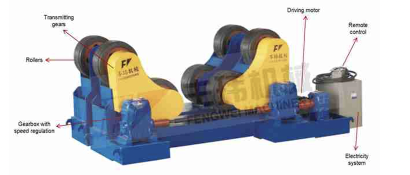
Structure of welding rotator
3. Detection of the axial movement of the weldment
The purpose of the detection of the axial movement of the weldment is to detect the movement displacement of the weldment in the axial direction. In principle, the detection method on the side of the weldment cylinder wall and the detection method on the end face of the weldment can be adopted. The side detection method of the cylinder wall can not be affected by the end face error of the weldment. However, this detection method needs to remove the vertical rotation component of the cylinder wall, plus the influence of slippage, the rough surface of the cylinder, and dirt, so it is necessary to produce a reliable sensor is not easy to come. The inspection method on the weldment end face is the current inspection method. This inspection is inevitably affected by the unevenness of the weldment end face and its axis perpendicular to the axis. Therefore, it is required to process the weldment end face to be tested. But for large weldments, the higher the precision required for this kind of processing, the greater the difficulty and cost. Whether it can reduce the requirements for end-face processing becomes important. For example, the process requires that the axial movement of the weldment is not greater than ±2mm, but the measured end surface unevenness of the weldment is greater than ±2mm. Under this condition, whether the axial movement of the weldment can be prevented is a measure of prevention. One of the important indicators of whether the welding rotator is practical or not.
 60 Tons self-aligned roller
4. Fuzzy control
For a weldment, especially for a large weldment, it is more difficult to know exactly the perpendicularity and unevenness of the inspection end surface relative to its axis. It is sometimes impractical to stipulate that the machining error of the end face does not exceed a certain value. Under this condition, how to achieve the purpose of anti-sweeping for different weldments, or even zero-sweeping, is the key. For control systems like anti-channeling welding rotators, when there are many uncertain factors that affect the axial movement of the weldment, fuzzy control can be used to achieve the control purpose. Fuzzy control is the use of computers to simulate the way of thinking of people, and control in accordance with human operating rules, that is, the use of computers to achieve human control experience. Fuzzy mathematics can be used to describe fuzzy concepts such as process variables and control actions and the relationship between them. Then, according to these fuzzy relationships and the detected values of the process variables at each moment, the method of fuzzy logic inference is used to obtain the control amount at that moment. . Fuzzification and precise control have a dialectical relationship. The computer imitates human thinking for fuzzy control, and the human brain’s important control experience is the fuzzy control rules composed of fuzzy conditional sentences. Therefore, it is necessary to convert the input signal from an accurate amount to a fuzzy amount. Fuzzification first converts the sampled value of the input signal to a point on the corresponding domain (range conversion) and then converts it into a fuzzy subset of the domain. Contrary to fuzzification, the process of defuzzification is to transform the fuzzy control effect obtained in the inference process into a precise control quantity.
However, for a control system where the detection end face error of the controlled weldment is greater than the accuracy of the anti-channeling, it is obviously not enough to solve the problem only by the method of fuzzy control theory in order to realize the purpose of anti-channeling of the weldment. Because the end face error of the weldment is greater than the requirement of anti-channeling accuracy, is the offset sent by the sensor caused by the error of the weldment end face or caused by the axial movement of the weldment, and the computer only sends it from The signal cannot be distinguished, and the error size and shape of different weldments are different.
5. Adaptive control
Adaptive control has the ability to modify its own characteristic parameters to adapt to changes in the dynamic characteristics of the controlled object and disturbance. In the adaptive system, the algorithm we use is the "parameter tracking algorithm". That is, the computer automatically tracks the sent signal and presets the action threshold. These parameters are not fixed during the control process. In layman's terms, let the computer remember the shape of the end face of the weldment first, and then distinguish the true amount of movement. In this way, the problem is simple, as long as the amount of movement is controlled and the end-face error is ignored. Following this idea, after a period of adjustment, "zero movements" of the weldment in its axial direction can be achieved. The length of the adaptive process depends on the end face error of the weldment. For weldments with an end face error of 5 mm, the amount of movement can be limited to within ± 2 mm after about 15 minutes, and the weldment can be maintained after about 0.5 hours. "Zero movements".


