


steel-structures
This section applies to the welding of carbon structural steel and low alloy high-strength structural steel with steel thickness greater than or equal to 3mm in industrial.

This section applies to the welding of carbon structural steel and low alloy high-strength structural steel with steel thickness greater than or equal to 3mm in industrial.
l Quality problems needing attention
l Environment, occupational health and safety management measures
This section applies to the welding of carbon structural steel and low alloy high-strength structural steel with steel thickness greater than or equal to 3mm in industrial and civil buildings and general structures such as truss or grid (shell) structure, multi-storey and high-rise beam-column, frame structure, etc. Applicable welding methods include manual arc welding, submerged arc automatic welding, nozzle electroslag welding, bolt welding, etc.
1.1 Technical preparation
(1) Before component fabrication, the factory shall prepare all kinds of construction processes and carry out welding process qualification tests according to construction plan and steel structure technical specifications as well as construction drawings and requirements of JGJ 81. The production and manufacturing process shall be strictly carried out according to the relevant parameters and requirements of the process evaluation. If the production quality is unstable according to the process evaluation specifications, the process evaluation shall be repeated to achieve the quality stability.
(2) New materials for minor selection in steel structure engineering must be qualified by new products. It can be used in engineering only after expert demonstration, review and welding process qualification.
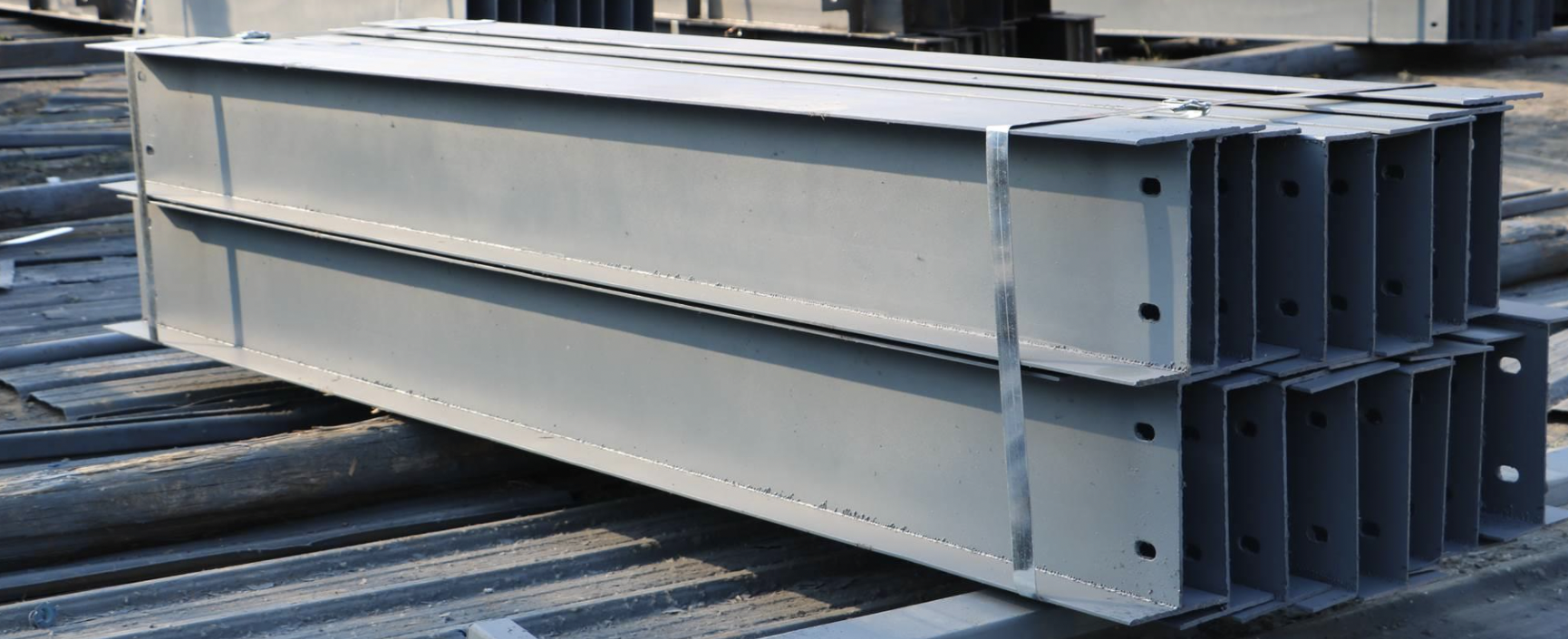 H-beam
1.2 Material Requirements
The selection of steel and welding materials for building steel structures shall comply with the requirements of the design drawings and shall have quality certificates or inspection reports issued by the steel and welding materials factories. When other steel and welding materials are used instead of the materials selected for design, the consent of the original design unit must be obtained.
(1) Selection principle of welding electrode
In manual arc welding, on the one hand, the electrodes can conduct welding current and arc initiation, at the same time, after melting, the electrodes directly transfer into the molten pool as filler metal, and fuse with the basic liquid metal to form the weld seam.
The appearance of the welding rod should not have defects such as peeling off and rusting of the core. The performance of the weld metal should meet the application requirements (meeting the design requirements). Generally, the mechanical properties (including tensile strength, plasticity and impact toughness) of the weld metal should meet the lower limit of the performance indexes specified in the base metal standard.
(2) Selection of welding electrodes for structural steel
A. According to the tensile strength of the base metal, the welding rods with the same tensile strength are selected according to the principle of "equal strength". When welding high-strength steel, the actual tensile strength of the weld metal is much higher than the nominal strength of the welding rod brand due to the influence of the base metal melter. Therefore, the welding rod with lower tensile strength can be selected to make the weld metal and base metal equally strong.
B. For base metal welding of different materials, the selection principle of electrodes is to match the low yield strength of base metal.
C. Alkaline electrodes with good plasticity, low hydrogen content and good crack resistance (i.e. low hydrogen electrodes) should be selected for important structures with high plasticity and toughness of crackable base metal or structure (high carbon equivalent or working thickness, high structural rigidity and low welding ambient temperature). Higher toughness and ultra-low hydrogen electrodes are the best choice to improve cold crack resistance of joints.
D. For pipe welding, vertical down welding, bottom welding, cover welding, etc., it is best to select special welding rods for pipe welding, vertical down welding rods, bottom welding rods and cover welding rods etc.
E. Alkaline electrodes (i.e. low hydrogen electrodes) without direct current welding power supply should be used. Low hydrogen potassium electrodes should be used.
F. Large structure, high depositing speed iron powder welding rod is available.
G. Selection of cast iron electrodes
(3) Select low cost cast iron welding rod according to type of cast iron, service requirements of workpiece and processing requirements.
A. When selecting welding rods, try to reduce costs as much as possible and select welding rods with high productivity and low cost, i.e. the principle of "low cost".
B. When selecting welding electrodes, it is necessary to consider that under the possible conditions of welding and groove processing, welding deformation should be minimized, welding electrodes should be saved, labor productivity should be raised and cost reduced. Generally, it is selected according to plate thickness.
2. Selection principle of flux
The choice of flux depends on the composition and properties of the base metal matching the welding wire.
(1) For carbon steel and ordinary low alloy steel, the mechanical properties of welds shall be guaranteed.
(2) For dissimilar steel joints of different strength classes, welding materials with better crack resistance can generally be selected according to steel with lower strength classes.
(3) The common combination of flux for welding wire is high manganese and high silicon flux (HJ 431) matching low manganese (H08A) or manganese (H08MnA) welding wire; Low or non-manganese high silicon flux is compatible with high manganese wire (H10Mn2).
(4) Flux should not be agglomerated by moisture. The flux must be dried before use. The drying temperature is generally 250 ~300 C for acidic flux (such as HJ 431 and HJ430) and the drying time is 2h. Alkaline flux (e.g. HJ 250, HJ 260) is generally 300 ~400 C and used after 2 hours of baking. The flux recovered in use should be screened, dried after debris removal, and then used in proportion to the new flux. The workshop should periodically recycle the flux to avoid waste.
3. The nozzle should not be visibly rusted or bent and the flux should not be wet and agglomerated. In order to ensure the stability of welding process, the pore diameter of fine wire conductive nozzle should not be larger than 0.1mm~0.25mm of wire diameter, and that of coarse wire welding conductive nozzle should not be larger than 0.20mm~O.40mm of wire diameter. The curvature radius in the wire feed hose must not be less than 150 mm.
4. Selection principles of welding screws
Made of low carbon alloy steel, it has reliable chemical composition, stable strength, good weldability and forging properties. Forging cracks should be prevented in use.
5. Welded ceramic rings are one-off auxiliary welding materials for bolt welding.
The ordinary peg nail welding of the workpiece and the common ceramic ring are used. The wall thickness of ceramic ring required for penetration welding is larger than that of common ceramic ring, and the total area of lower exhaust holes is 1.3 times that of common ceramic ring.
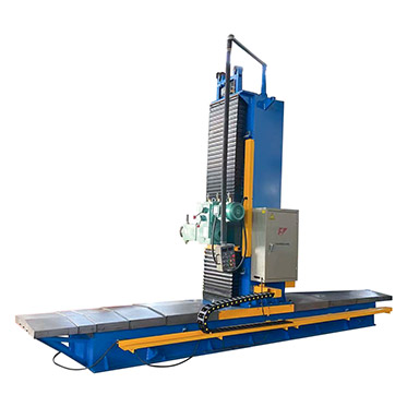
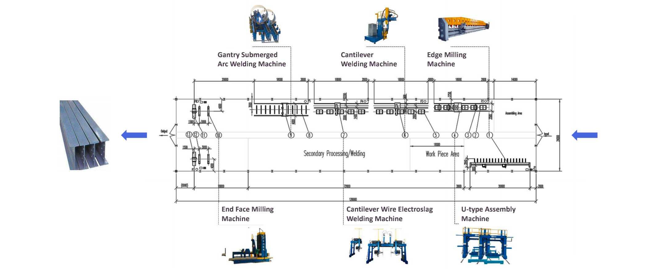
1.3 Main Machinery
(1) Main welding tools: electric air compressor, diesel generator, DC welder, AC welder, submerged arc welder, electrode drying box, welding roller frame, electroslag welder for fuse nozzle, flange straightener, etc.
(2) Other equipment: theodolite, ultrasonic flaw detector, digital thermometer, film thickness gauge, digital clamp-on ammeter, wet temperature gauge, weld inspection ruler, magnetic particle flaw detector, steel ruler, box ruler, steel plate ruler, vernier caliper, hammer, marking pen, air cutting gun, oxygen, acetylene, electric grinding wheel, etc.
1.4 Operating Conditions
(1) The welding area shall be dry and free from oil, rust, water, scale and other contaminants.
(2) The welding rods and flux shall be baked according to the baking time and temperature specified in the product specification before they are used. Low hydrogen type electrodes must be stored in an insulating box (cylinder) after drying and can be used as needed. The time from removing the welding electrode from the heat preservation tank (cylinder) to welding should not exceed 2 h (acid electrode should not exceed 4 h). If the above requirements are not met, they should be re-dried and reused, but the welding rod should not be dried more than 2 times.
(3) When wind speed in welding work area exceeds 8m/s, gas shielded arc welding and flux-cored arc welding exceed 2m/s, wind shield or other wind protection measures shall be taken. When there is cross-hall air or blower in the welding work area of the production workshop, the windscreen device shall also be provided as specified above. Relative humidity in the welding work area shall not exceed 90%. When the surface of the weldment is wet or covered with ice and snow, heating, dehumidification and moisture removal measures shall be taken.
(4) When the ambient temperature in the welding work area is lower than 0 C, the base metal in each direction of the welding area of the member shall be more than or equal to twice the thickness of the steel plate and not less than 100 mm. The welding can be carried out only after heating to more than 20%, and the actual heating temperature shall not be lower than this temperature during the welding process. The actual heating temperature shall be based on the structural characteristics of the member, the type of steel, the quality grade and the welding performance. The diffusion hydrogen content of deposited metal of welding material, welding method and welding heat input etc. are determined. The heating temperature should be higher than the preheating temperature of welding at normal temperature, and the work plan can be implemented only after it is approved by the welding technical responsible personnel. The work plan shall ensure that the welder's operating skills are not affected by low ambient temperatures and that necessary insulation measures are taken for the components.
(5) Before welding, the welder shall check the joint quality of the welded parts and the treatment of grooves, gaps and blunt edges in the welding area. When any non-conformance is found, the welding shall be performed after repairing the integration grid.
(6) Wire should be carefully cleaned before welding to remove impurities such as rust and oil.
(7) The nozzle should not be obviously rusted and bent. It should be dried at 250 C for 1H before use and stored at 80 C or so. The pegs and matching ceramic rings should also be baked and dehumidified before use.
(8) The coiling of welding wire should be neat and tight, free from hard bending, rust and oil stain. The minimum amount of wire on the wire disc must be no less than the amount of wire required to weld a weld.
(9) All parts of the welding machine shall be in normal working condition.
(10) Ensure the supply and stability of power supply and avoid excessive power cut-off and voltage fluctuation during welding.
(11) A welder must pass the examination and obtain a certificate. A certified welder must perform the welding within the qualified items and the approved scope of the examination.
2.1 manual arc welding
1. Scope of application
All three actions of electrode feeding, advancing and swinging are realized by manual operation, which are called manual arc welding. It is the most basic welding method in fusion welding. It has the characteristics of simple equipment, convenient and flexible operation and so on. It is widely applicable to the steel structure manufacturing, installation and welding process of truss or grid (shell) structure, multi-storey or high-rise beam, column, frame structure and other industrial and civil buildings and general structures. It is the most basic and main welding method in the welding industry at present.
2. Process flow
3. Operation process
(1) Selection of welding parameters
a. Selection of electrode diameter
The diameter of welding rod is mainly selected according to the thickness of weldment. Generally, the greater the thickness of weldment, the larger the diameter of welding rod
For the first layer of multi-layer welding and welding in non horizontal position, the electrode diameter shall be smaller. Under the condition of the same thickness, the diameter of the electrode for flat welding can be larger than that for other positions. The maximum diameter of the electrode for vertical, horizontal and overhead welding positions generally does not exceed 4mm. For the welding rod for welding the circumferential seam of the pipeline at the fixed position, in order to adapt to the operation at various positions, the small-diameter welding rod should be used. For some weldments requiring to prevent overheating and control energy limitation, small-diameter electrodes should be selected.
b. Selection of welding current
The current is mainly selected according to the diameter of welding rod. There are two methods:
Method 1: check the welding current selection table, as shown in table 7-2.
Method 2: there is an approximate empirical formula for estimation:
I=(30~55)d
Where: D -- electrode diameter, mm;
I -- welding current, a.
When welding fillet weld, the current shall be slightly larger; When backing welding, especially when welding single side welding and double side forming weld bead, the welding current shall be small; When filling welding, large welding current is usually used; During cover welding, in order to prevent undercut and obtain a more beautiful weld, the current used is slightly smaller.
The welding current of alkaline electrode is about 10% less than that of acid electrode. The current of stainless steel electrode is about 20% less than that of carbon steel electrode. After the welding current is preliminarily selected, it shall be adjusted through trial welding.
c. Selection of arc voltage
The selection of arc voltage mainly depends on the arc length. If the arc is long, the voltage is high; On the contrary, it is low. In the welding process, it is generally expected that the arc length will always be consistent, and short arc welding shall be used as far as possible (the so-called short arc refers to that the arc length is 0.5-1.0 times the diameter of the electrode). Generally, good welding effect can be obtained by short arc and low pressure operation of low hydrogen electrode.
d. The selection of welding process parameters should adopt large-diameter electrode and high current welding under the condition of ensuring welding quality, so as to improve labor productivity.
e. For welds and joints with high performance requirements, the thickness of each layer of weld shall not be greater than 4mm.
f. The weld bead at the bottom of the groove should be no more than φ For 3.2mm electrode, the minimum size of the bottom root pass shall be appropriate to prevent cracks.
g. Under dynamic load, the weld reinforcement h of welded joint shall tend to zero. Under other working conditions, H value can be selected in the range of 0 ~ 3mm.
h. The coverage width of the weld at the seaside of the welded joint shall not be less than 2mm ~ 4mm.
(2) Before welding, the welder shall review the joint quality of the weldment and the treatment of groove, gap and blunt edge in the welding area. In case of any nonconformity, it shall be repaired and qualified before welding.
(3) During welding, the electrode with coating falling off or welding core rusting shall not be used.
(4) Both ends of main welds of T-joints, cross joints, corner joints and butt joints must be equipped with arc striking plates and arc extinguishing plates, and their materials and groove forms shall be the same as those of weldments. The length of arc striking and arc extinguishing welds shall be greater than or equal to 25mm. The length of arc striking and arc extinguishing plates shall be greater than or equal to 60mm, the length shall be 1.5 times of the plate thickness and shall not be less than 30mm, and the thickness shall not be less than 6mm. Arc striking and arc extinguishing plates shall be cut off by gas cutting, polished and leveled, and shall not be knocked down by hammer.
(5) The welding area shall be kept dry and free of oil, rust and other dirt.
(6) The welding rod shall be baked according to the baking time and baking temperature specified in the product manual before use.
(7) Ignition and arc striking shall not be conducted on the base metal other than the weld.
(8) When the ambient temperature of the welding operation area is lower than o ℃, the base metal in each direction of the component welding area greater than or equal to the thickness of the steel plate and not less than 100mm shall be heated to above 20 ℃ for welding, and shall not be lower than this temperature during the welding process.
(9) Process measures for tack welding
The model of welding material used for tack welding shall match the material of weldment. Tack welding must be carried out by welders with corresponding certificates, and the tack weld shall have the same quality requirements as the final weld.
a. The thickness of tack weld shall not exceed 2 / 3 of the design weld thickness and shall not be greater than 6mm. During long weld welding, the length of tack weld shall not be less than 50mm, the weld spacing shall be 500mm ~ 600mm, and the arc pit shall be filled.
b. The position of tack welding shall be arranged within the weld bead. In case of weld intersection, the tack weld shall be more than 50mm away from the intersection.
c. The reinforcement of the tack weld shall not be too high, and both ends of the tack weld shall transition smoothly with the base metal to prevent incomplete penetration and other defects during formal welding.
d. If the tack weld is cracked, the weld at the crack must be removed and re tack welded. After tack welding, if the interface is uneven, it shall be corrected before formal welding.
e. The tack weld shall be free of crack, slag inclusion, weld bead and other defects. Harmful substances in the welding area must be removed before welding.
f. The preheating temperature of tack welding shall be higher than the formal welding temperature.
g. When there are pores or cracks on the tack weld, it must be removed and re welded.
(10) Process measures of multi-layer welding
a. During multi-layer welding of thick plates, continuous welding shall be carried out. After each welding pass is completed, the welding slag and surface spatter shall be cleaned in time. When defects affecting the welding quality are found, they shall be removed before welding. During continuous welding, the base metal temperature in the welding area shall be controlled to make the upper and lower limits of the layer temperature meet the requirements of the process documents. In case of interruption of welding, appropriate post heating and thermal insulation measures shall be taken. During re welding, the re preheating temperature shall be higher than the initial preheating temperature.
b. The diameter of the electrode used for the bottom weld bead of the groove shall not be greater than φ 4mm, the minimum size of the root pass of the bottom layer of the electrode shall be appropriate, but the maximum thickness shall not exceed 6mm.
2.2 Automatic submerged arc welding
(1) Scope of application
Submerged arc welding (SAW) is a welding method using arc as a heat source. When welding, the arc burns under the granular flux to complete the welding process. Because of its deep penetration, fast welding speed, mechanized operation and high productivity, submerged arc welding is widely used for long welds of medium-thickness plates. Weldable carbon steel, low alloy steel, stainless steel, heat-resistant steel and its composite steel. However, due to the use of granular flux, it is generally only suitable for flat welding.
(2) Process Flow
(3) Operating Technology
A. Selection of process parameters for submerged arc automatic welding
The selection of welding current can be estimated according to an approximate empirical formula.
H=KI
In equation: h--penetration depth, mm;
K-coefficient, which is determined by current type, polarity and wire diameter, is usually O.01 (DC direct connection) or 0.0ll (DC reverse connection, AC);
I--Welding current, A.
B. The appropriate wire diameter can be selected according to the welding current
C. Arc voltage to match welding current
(2) In addition to determining welding parameters according to above items, parameters such as welding current, arc voltage, welding speed and wire feed speed should be adjusted according to the requirements of process documents before welding can be formally performed.
(3) Plates less than 12mm thick, without groove, are welded on both sides with slightly higher welding current on the front, penetration of 65%-70% and reverse of 40%-55%. For plates with thicknesses greater than 12mm to 20mm, clean the roots on the back and weld them after one-sided welding. For plate with large thickness and groove welding, manual backing welding is usually used.
(4) When multi-layer welding, the height of each layer is 4 mm~5 mm. When multi-pass welding, the welding wire is 3 mm~4 mm away from the groove surface.
(5) The total thickness of the filler layer is lower than lmm~2mm of the base metal surface, slightly concave, and the groove edge must not be melted.
(6) Cover layer makes the width of weld to groove 3?Lmm on each side, and adjusts the welding speed so that the residual height is 0~3mm.
(7) Arc-striking plate and arc-extinguishing plate are added to both ends of the weld bead. The length of the arc-striking and arc-extinguishing seam shall be greater than or equal to 80mm. The length of arc-striking and arc-extinguishing plates shall be greater than or equal to 150 mm. Arc initiation and arc extinguishing plates shall be cut by gas cutting and ground flat. They shall not be knocked down by hammer.
(8) Forming factor (width: depth) of cross section of deposited metal in each submerged arc welding seam shall be greater than 1.
(9) Before welding, the welder shall check the joint quality of the welded parts and the treatment of grooves, gaps and blunt edges in the welding area. When any non-conformance is found, the welding shall be performed after repairing the integration grid.
(10) Arc ignition shall not be applied to the base metal other than the weld.
(11) The type of welding material used for positioning welding shall match the material of the welding part.
A. The size of the positioning foot should not exceed 2/3 of the design weld thickness and should not exceed 6mm. When welding a long weld, the length of the positioning weld should not be less than 50 mm, the distance between the welds should be 500 mm to 600 mm, and the arc pits should be filled.
B. Location welding should be placed within the bead. In case of weld cross, the positioning weld should be more than 50mm away from the cross.
3. The excess height of the positioning weld should not be too high. The two ends of the positioning weld should transition smoothly with the base metal to prevent defects such as final penetration during formal welding.
4. If the positioning weld cracks, the weld at the crack must be removed and re-positioned. After positioning welding, if uneven joints occur, corrections should be made before formal welding can take place.
5. The positioning weld shall be free from defects such as cracks, slag inclusion and weld beads. Harmful substances in the welding area must be removed before welding.
(12) For non-sealed concealed parts, the coating treatment shall be carried out according to the requirements of construction drawings before assembly can be carried out; For planing top-tight parts, welding can only be carried out after passing inspection by quality department.
(13) Welding on assembled components shall be carried out strictly in accordance with the welding process parameters and welding procedures to control the deformation of the components after welding.
(14) Members deformed by welding may be corrected by mechanical (cold straightening) or heating (heat straightening) under strictly controlled temperature conditions.
2.3 Electroslag welding of molten nozzle
(1) Scope of application
It is applicable to thick plate butt joint and corner joint of building structure, especially factory joint of box column panel and built-in diaphragm in high-rise steel structure. Due to the better preheating effect of slag pool on the welded workpiece, electroslag welding with fuse nozzle is also suitable for welding some metals with poor welding performance such as high carbon steel and cast iron.
(2) Process Flow
(3) Operating Technology
A. Arc-striking plate and arc-extinguishing plate shall be set at both ends of weld bead according to process requirements. Generally, the length of arc-striking plate shall be 2-2.5 times of plate thickness and the length of arc-extinguishing plate shall be 1.5-2 times of plate thickness.
B. Install the tubular nozzle and adjust the alignment. The distance between the lower end of the nozzle and the bottom of the arc-striking plate is generally 15mm~25mm.
C. The selection of welding current can be calculated according to empirical formulas.
D. Voltage is proportional to the width of the weld. Voltage is slightly higher at the arcing stage, usually 50-55V. It is convenient to melt the edge of the base metal and form a stable electroslag process as soon as possible. With the penetration guaranteed, the voltage should be as low as possible. Normal welding requires a slightly lower voltage, which can generally be selected between 35 and 55V. Welding voltage varies with the welding process. Always pay attention to adjusting the voltage during welding.
E. The welding speed can be selected in the range of 1.5-3m/h.
F. The commonly used wire feeding speed range is 200-300m/h, and 200m/h is suitable for slag making.
G. The depth of slag pool is proportional to the resistance heat generated. The heat generated by the stable depth of slag pool is stable and the welding process is stable. The depth of slag pool is generally 35 mm to 55 mm.
H. When starting the welding, slowly put in a small amount of flux, generally 35-50g. During the welding process, a small amount of flux should be added gradually.
I. The cooling water temperature should be controlled at any time between 50 ~60 C, and the water flow should be kept stable.
J. During welding, check whether the nozzle is in the center of the bead at any time. Excessive deviation of the nozzle and welding wire is strictly prohibited.
K. Pay attention to checking the hot state of the weldment at any time during the welding process. Generally, the fusion is good at more than 800t (cherry red). When the temperature is less than 800 C, the welding parameters should be adjusted properly to increase the total heat in the slag tank.
L. When the thickness of the weldment is less than 16mm, a copper radiator or a circulating water radiator should be installed outside the weldment.
M. When closing the weld, the welding voltage should be reduced appropriately and the welding wire should be fed intermittently to lead the weld to the end of the arc extinguishing plate.
N. The electroslag welding of the fuse nozzle does not carry out pre-welding and post-welding heat treatment, but only heats the arc initiator at about 100 C before arc striking.
O. Members deformed by welding may be corrected mechanically or by heating under strictly controlled temperature conditions.
2.4 stud welding
(1) Scope of application
It is applicable to all kinds of steel structure projects (such as the welding of shear parts, embedded parts and anchors in steel columns, beams, externally cast concrete and steel-concrete composite floor slab, and the weldable diameter of studs can reach 22mm).
(2) Process flow
(3) Operation process
Preparation before welding: setting out, sampling inspection of stud and porcelain ring, drying. Weldments shall also be dried in humid environment.
Pre welding test: two test pieces shall be made before formal welding every day, and the formal welding can be carried out only after the 45 ° bend is checked and qualified.
(4) Determine process parameters
Before stud welding, the stud produced by different materials, different specifications, different manufacturers and different batch numbers must be strictly tested with process parameters under the same conditions on site with different models of welding machines and welding guns.
a. Static tensile test: use 20 ° cable-stayed method to check the displacement, tensile strength, elongation and yield point during tensile fracture.
b. Repeated bending test: repeatedly bend more than 45 ° in a longitudinal plane, and there shall be no fracture around the weld.
c. Bend like. Angle test: the weak part of the weld shall not crack.
The process parameters passing the above process tests can be used in the project. The welding energy is directly proportional to the product of welding voltage, current and time. In order to ensure the stability of stud welding arc, the welding energy should be controlled and changed by adjusting the welding current and energizing time.
d. Stud test must be conducted by welders with rich practical experience under the supervision of welding engineers.
(5) Key points of operation:
a. The welding gun shall be at an angle of 90 ° around the workpiece, the porcelain ring shall be in place, the welding gun shall clamp the stud and put it into the porcelain ring for compaction.
b. Pull the switch of the welding gun, the current will generate an arc through the arc striking agent, the stud will melt within the control time, press down with the gun, rebound and arc break, and the welding is completed.
c. Wait a minute, knock off the porcelain ring with a small hammer.
d. Penetration welding adopts the following methods:
① Non galvanized plates can be welded directly.
② The galvanized sheet shall be baked at the stud welding position with acetylene oxygen flame, and the zinc shall be removed on both sides after knocking.
③ Auger shall be used for drilling.
3.1 main control items
(1) The matching of welding materials such as welding rod, welding wire, flux and electroslag welding nozzle with the base metal shall meet the design requirements and the provisions of the current national industrial standard technical specification for welding of building steel structures (JGJ 81). Welding rods, fluxes, flux cored wires, welding nozzles, etc. shall be baked and stored according to the product instructions and welding process documents before use. The appearance of welding rod shall be free of defects such as coating falling off and welding core rusting; The flux shall be free from moisture and caking.
(2) Welders must pass the examination and obtain the qualification certificate. The certified welder must conduct welding within the examination items and the approved scope.
(3) The construction unit shall conduct welding procedure qualification for the steel, welding materials, welding methods and post weld heat treatment used for the first time, and determine the welding procedure according to the qualification report.
(4) For class I and II welds with full penetration as required by the design, ultrasonic flaw detection shall be used to inspect the internal defects. If ultrasonic flaw detection cannot judge the defects, radiographic flaw detection shall be used. The classification and flaw detection method of internal defects shall comply with the current national standard manual ultrasonic flaw detection methods and classification of flaw detection results for steel welds (GB 11345) or Radiographic and quality classification of fusion welded butt joints of steel (GB 3323).
The internal defect classification and flaw detection methods of welded ball joint space truss welds, bolt ball joint space truss welds and circular tube T, K and Y-joint related line welds shall respectively comply with the current national standards ultrasonic flaw detection methods and quality classification methods for welded ball joint steel space truss welds (jbj / T 3034.1) and ultrasonic flaw detection methods and quality classification methods for bolt ball joint steel space truss welds (jbj / T 3034.2) and technical specification for welding of building steel structures (JGJ 81).
(5) The weld surface shall be free of cracks, weld beading and other defects. The primary and secondary welds shall be free of surface pores, slag inclusion, crater cracks, arc scratches and other defects; and the primary welds shall be free of undercut, incomplete welding, root shrinkage and other defects.
(6) The construction unit shall conduct welding procedure qualification for the welding of welding nails and steel, and the results shall meet the design requirements and the provisions of relevant current national standards. The porcelain ring shall be baked according to its product manual.
(7) Bending test shall be carried out after welding nails, and there shall be no visible cracks in the weld and heat affected zone.


